
CENTRIFUGATION
Centrifugation
is a basic separation technique. A centrifuge is a device for separating
particles in an applied centrifugal field in a solution.
There are two
different forces act on an object moving in a circular motion.
Centrifugal force:
Force
directed outward from the center. E.g. While
turning a bus in twist way, the passengers strike on the bus wall is due to
centrifugal force.
Centripetal
force:
The
force exerted towards the center is now as centripetal force. E.g. the force acts
on passengers by the turning car.
Now, suppose
a particle is exerted to sediment by centrifugal force, then
The rate or
velocity at which it sediments is proportional to the force applied
- Sedimentation
is more rapid when the force applied is greater than the gravitational
force of the Earth
- Basis of
separation is to exert a larger force than does the Earth’s gravitational
force.
Basic
Principle of Sedimentation
The
particles to be separated are suspended in a specific liquid media, held in
tubes or bottles which are located in rotor in centrifuge machine, positioned
centrally to the drive shaft. These particles are differing in size, shape and
density.
As
we have already mentioned that,
The rate of
sedimentation is dependent upon the applied centrifugal field (G)
G = W2R …………………………equ
(i)
Where
W: Angular velocity of revolving particle
(Remember: one revolution of the rotor is equal to 2 radians)
R: Radial
distance from axis of rotation
In terms of revolution per minute, we have W= 2p rev min-1/ 60
Therefore:
G = W2R
It
is expressed as a multiple of the earth’s gravitational field (g=981 cm s-2).
Hence
RCF,
Relative Centrifugal Field
= G / g
=
RCF = 1.119 x 10⁻⁵(rev min-1)2 R …………………………….equ (ii)
= x g unit
(number times g)
It
means, RCF is the ratio of the weight of the particle in the applied
centrifugal field to the weight of the same particle when acted by gravity
alone. Therefore the rotor speed, radial dimensions and time of the rotor must
be quoted during the centrifugation.
However:
This
is not the only case in Biochemical experiments as biological samples are
always found in dissolved or suspended form in a solution. Thus, the rate of
sedimentation not only depends on the centrifugal field but also on
1. Mass of particle
2. Density of particle
3. Density and viscosity of the medium
used
4. The extent to which its shape deviates
from spherical
Now according to Newton’s Second law of Motion, the centrifugal force (F) exerted on particle is
= M. a
= M. W2R
……………………………….equ
(iii)
Where:
M: mass of
particle
a:
acceleration while in angular motion= W2R
Increasing
the sharpness of a turn, w and r decreases. Since r is linear, w has greater
effect on the particle.
It
causes the molecules to sediment down the centrifuge tube. They start to move
downward to sediment; however they encounter opposing force, a frictional
resistance in their movement.
Frictional
force = f
= 6p. h. Rp.
) ……………………………equ (iv)
Where:
f: Frictional force
dr/dt: Rate
of sedimentation expressed as the change in radius with time (velocity v)
h: Viscosity coefficient of medium
Rp: Radius
of sedimenting particle
The
sedimenting molecule must also displace the solvent into which it sediments and
give rise to a buoyant force
Buoyant force =
mass x a
= V. dm W2R ……………………..equ (v)
Where:
V: Specific volume of the molecule
dm: Density of
the medium
While
sedimenting, the velocity of the particle increases until it equals the
frictional force resisting its motion through the medium. This is an
equilibrium state when the particles stop to move or sediment. From equations
iii, iv and v.
Centrifugal force =
Frictional force + Buoyant force
M. W2R =
6p. h. Rp.
) + V. dm W2R
v =
h Rp2 (dp - dm) W2R ……………………………..equ
(vi)
Where:
dr/dt: v, is
the velocity of the sedimenting particle
Mass: Density x Volume
dp: Density of particle
dm: Density of
medium
From above equation, it seems clear that velocity is proportional to its size, to the differences in density between the particle and medium and to the applied centrifugal field. It is zero when the density of the particle and medium are equal. It decreases when the viscosity of the medium increases.
Since the Rp is in square form, the size of particle has greater influence on velocity.
For
a particle, h, Rp, dp, dm and W all are
constants
t =
In
Where
t: The sedimentation time in seconds
Rt: Radial distance from the axis of rotation
to liquid meniscus
Rb: Radial
distance from the axis of rotation to bottom of tube
It is now clear that a mixture of heterogeneous approximately spherical particles can be separated by centrifugation on the basis of their densities, their sizes and etc.
t µ
It means, higher the size particles, faster is the sedimentation (Short time for sedimentation) of it and smaller the size slower is the sedimentation (takes longer time).
CENTRIFUGATION: RCF CALCULATION
The relative centrifugal force (RCF) can be calculated from
the following equation:
RCF = (1.119 x 10⁻⁵) (rpm)2(r)
Where rpm is the speed of rotation expressed in revolutions per
minute and r (radius) is the distance from the axis expressed in cm. The RCF
units are "x g" where g represents the force of gravity. RCF
can also be determined from the NOMOGRAPH
below. Place a straight edge to intersect the radius and the desired RCF to
calculate the needed rpm. Alternatively place the straight edge on the radius
and the rpm to calculate the g-force. For example, spinning a sample at 2500
rpm in a rotor with a 7.7 cm radius results in a RCF of 550 x g.

Figure 1: Nomograph
showing relationship between RCF, RPM and Radius
Centrifuges and their uses
Centrifuges and their uses
1.
Low Speed Centrifuge
·
Least expensive and simplest in many design
·
Maximum rotor speed of 4000-6000rpm (3000-7000 X g)
a) Small
bench centrifuges
·
To collect small amounts of materials (250mm3) that is
rapidly sediment (1-2 min)
·
No special cooling system
·
Ambient air flows around the rotor to cool the system
·
Use to rapid sedimentation of blood samples
b) Large
capacity refrigerated centrifuges
·
Refrigerated rotor chambers for cooling the sample
·
Large volumes 10, 50 and 100 cm3 processing depending
upon the rotors and tubes
·
Maximum capacity of 1.25 dm3
·
Rotors are mounted on a rigid suspension
·
Erythrocytes, coarse or bulky precipitates, yeast cells, nuclei
and chloroplasts
2. Microcentrifuge
·
Maximum rotor speed of 12000rpm with RCF of 10000g
·
Have total capacity of 1.5ml over very short time (0.05-5 min)
·
Use to sediment large particles like cell ppt
3. High speed refrigerated centrifuge
·
Maximum rotor speed of 25000rpm with RCF of 60000g
·
Have total capacity of 1.25 dm3
·
Interchangeable fixed angle and swinging buckets rotors
·
Use to collect microorganisms, cellular debris, larger cellular
organelles and proteins precipitates by ammonium sulphate
·
Not use for viruses and smaller organelles like ribosome
4. Continuous flow centrifuge
·
Relatively simple and high speed centrifuge
·
Special design rotor (long and tubular) with non interchangeable
system
·
Have total capacity of 1-1.25 dm3/min with continuous
flow
·
Particles sediment at wall and excess clarified medium overflows
through an outlet port
·
Use to collect bacterial and yeast cells from their mass culture
of about 100-500 dm3
5. Ultracentrifuge
·
Powerful with speed
·
2 types
a) Preparative ultracentrifuge
- Maximum rotor speed of 30000-80000 rpm
with RCF of 600000 x g
- Highly sophisticated with refrigerated,
sealed and evacuated to minimize excess heat generate
- More sophisticated temperature
monitoring system employing an infrared temperature sensor
- Overspeed control system to prevent
operation of rotor above its max rated speed
- Vibration minimize system (a flexible
drive shaft system) during unequal loading of the centrifuge tubes
- Enclosed in heavy armour plating
- Airfuse for some biochemical
applications requiring high centrifugal force
- Use for sediment macromolecule/ligand
binding kinetic studies, steroid hormone receptor assays, separation of
major lipoprotein from plasma and deproteinisation of physiological
fluids for amino acid analysis
b) Analytical ultracentrifuge
- Maximum rotor speed of 70000 rpm with
RCF of 500000 x g
- Highly protective chambers with
refrigerated and evacuated system also have an optical system to enable
the sedimenting material to be observed throughout the process.
- Three types of optical system, a light
absorption system, alternative Schlieren system and Rayleigh
interferometric system (both measures refractive index of solution)
Design and types of Preparative Rotors
- These are rotating instruments in
Centrifuges
- During rotation at high speed, higher
stress forces generated
- Made up of aluminum alloy and titanium
alloy which don’t rust-brass, steel or Perspex
- Can tolerate nearly twice the centrifugal
force of rotors
- Protective coating to the metal surface
by anodizing or by applying black epoxy paint
- Various types of rotors
a)
Swing bucket
rotors
·
Common in low speed centrifuges
·
Also high speed, ultracentrifuges
·
Tubes accommodated
in a pivoted bucket which rotates from a vertical to a horizontal position
during acceleration
·
Bucket returns to vertical as centrifuge decelerates
·
Meniscus of sample always remains at right angles to axis
of tube
·
Six-place rotor (6 buckets) most useful – can spin 2,3,4 or
6 samples (or sets of samples)
·
Pelleted material symetrically distributed in a
hemisperical section at bottom of tube
·
Only particles in bottom of tube which move directly to
bottom
·
Other particles move first to wall of tube, then towards
bottom

Figure 2:
Swinging-bucket rotor and its spinning
b)
Fixed-Angle Rotors
·
Tubes in pocket at fixed angle in rotor
·
Angle 10 to 50 degrees from vertical – at rest and during
spin
·
Use up to 600,000 x g
·
Particles migrate to wall before moving towards bottom
·
Pellets always asymetrically distributed toward the outer
aspect of the bottom of the tube
V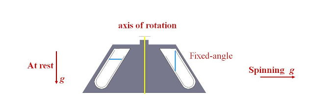

Figure 3: Fixed-angle
rotor
c)
Vertical Rotors
·
First introduced in 1970’s – high-speed and
ultracentrifuges
·
Solution re-orientates below 800 rpm, no disruption to
gradient
·
Good for isopycnic and rate-zonal centrifugation
·
Not used for pelleting – pellet would be along length of
tube and would fall off as liquid decanted
·
Also – “near-vertical” rotors – tube angle = 8 degrees

Figure 4: Vertical or near
vertical rotor

Figure 5: Axis of rotation
SEPARATION METHODS IN PREPARATIVE ULTRACENTRIFUGATION
1.
Differential Centrifugation: The process of differential centrifugation is based on the fact
that organelles have differences in size, shape and density. As a result, the
effect of gravity on each is different. We can use this principle to separate
an organelle from a homogenous solution of particles by artificially
controlling the gravity of a solution. This is done by putting the solution in
a variable speed centrifuge and rotating them at a high rate of speed. This
creates a force that can be much greater than the force of gravity, and
particles that would normally stay in solution will fall out and form a pellet
at the bottom of the tube.
Differential centrifugation
schemes involve stepwise increases in the speed of centrifugation. At each
step, more dense particles are separated from less dense particles, and the
successive speed of centrifugation is increased until the target particle is
pelleted out. The final supernatant is removed, the pellet is resuspended and
further study or purification can be done on it. The fractionation of rat liver
is an example of how this process works:

Figure 6: Separation
of cell fractionate by Differential Centrifugation

Figure 7: Separation of cell organelles from rat liver fractionate by Differential Centrifugation
2. Density Gradient Centrifugation
Density
gradient centrifugation is a technique that allows the separation of cells,
organelles and macromolecules, depending on their size, shape and density.
A density gradient is created in a
centrifuge tube by layering solutions of varying densities with the dense end
at the bottom of the tube. Cells and large molecules are usually separated on a
shallow gradient of sucrose or other inert carbohydrates even at relatively low
centrifugation speeds, while macromolecules such as proteins and nucleic acids
are separated at higher centrifugation using ultracentrifuges.
Criteria for an ideal density gradient centrifugation medium are:
- the
additive must form a solution within the required density range
- the
additive must not interfere with, or damage, the sample
- the solvent
must be compatible with the sample
- the
solution must have a refractive index within the practical range, as well
as a low viscosity
- The
additive must be easily removable from the sample.
The additives for density gradient centrifugation can be divided
into four main categories:
These
solutions fulfill most of the above requirements. However, due to the high
ionic strength, hydrogen bonding within biological macromolecules (protein,
nucleic acid - protein complexes) is impaired by a chaotropic effect. Therefore
these salts are mainly used for DNA and RNA separations. Cesium chloride is
used most frequently. Other useful salts include sodium iodide, sodium bromide,
cesium sulfate and cesium acetate. Potassium tartrate has been used to separate
viruses from host cells.
It should be kept in mind that the density of the sample is highly dependent on the hydration of the macromolecule, which in turn depends to a large extent on the dehydration power of the salt solution.
In this class
of compounds sucrose is most widely used. It has a useful density range of up
to 1.29. This range can be increased to 1.37 by addition of glucose or by
dissolving sucrose in D2O. Sucrose has very little effect on
macromolecules, but affects enzyme activity. Due to its high osmotic pressure,
sucrose solution dehydrates cells and their organellae very efficiently.
Glycerol solutions are the preferred media for the separation of enzymes
because they do not affect enzyme activity. They exhibit a high viscosity,
requiring prolonged centrifugation times. More importantly however, glycerol
penetrates biological membranes.
3.
Hydrophilic Macromolecules
Dextran
gradients have been used for the separation of microsomes. Separations achieved
with dextrans show similar results to those obtained by using synthetic
sucrose/ epichlorohydrin co-polymers. In some cases bovine serum albumin has
been applied, but the preparation of an appropriate solution is very difficult.
4.
Synthetic Molecules
These
additives are the sodium or methyl glucamine salt of triiodobenzoic acid and of
metrizoic acid. It should be kept in mind that the parent acid of these salts
may precipitate on adjusting the pH to acidic values. Metrizamide, a covalently
bonded compound of glycosamine and metrizoic acid is most widely used. This
additive forms solutions of relatively low viscosity. These solutions are
stable over a wide range of pH and ionic strength, and show practically no
interference with the analytes.
Density gradient centrifugation
methods are of two types, the rate zonal technique and the isopycnic
(isodensity or equal density) technique.
Rate
Zonal Technique: When mixtures of cellular extracts are layered on top of a
density gradient in a tube and subjected to centrifugation, the various
components move through the gradient at different rates that are dependent on
their sizes and shapes. These different components appear as distinct bands or
zones in the gradient with large components migrating farthest in the tube in a
given period of time. The rate with which a fraction moves the fixed distance
in the gradient tube is dependant of its sedimentation value (S) that, in turn
is determined by the size and shape of that fraction. By comparing the
different position of the components in the gradient, it is possible to make an
approximate measurement of their molecular weight. It is, however, difficult to
precisely determine these molecular weights, as this requires knowledge about
the shape of these molecules, which is hard to determine with accuracy. This
density gradient separation technique is called rate zonal centrifugation and is
usually performed with a shallow sucrose gradient. The different components
being separated by this technique are denser than any of the sucrose
concentrations used in the gradient. Samples are, therefore, centrifuged just
long enough to separate the components of interest. Longer centrifugation than
necessary would allow all components to form a pellet at the bottom of the
tube. One of the most important applications of this technique over the past
decades was the separation of transfer RNA (4S) from ribosomal RNA
that forms three different classes with distinct sedimentation values 23S, 16S
and 5S. This helped to facilitate the characterization of the protein
synthesizing system.

Figure 8:
Rate zonal Density Gradient Centrifugation
Isopycnic
Technique: A second density gradient technique, called equilibrium
density-gradient centrifugation is used to separate cellular components on the
basis of their buoyant density. In this case the cellular mixture is
centrifuged through a steep density gradient that contains a high concentration
of sucrose, or more often, cesium chloride (CsCl). In these gradients, the
molecules being studied have a density somewhere in between the highest and
lowest densities of sucrose or CsCl generated in the gradient. The components
of a sample begin to move down this gradient in the same way as they do in a
rate-zonal density gradient. When a component of the mixture reaches a point where
the density of the solution is equal to its own density, it stops moving
further and forms a distinct band. The position of the band in the tube is
characteristic of the buoyancy of that component. Buoyancy or buoyant density
of a substance is its tendency to float in a medium, which in this case is the
density gradient. Hence soluble proteins which have similar density (p=1.3 g cm-3
in sucrose solution) cannot usually be separated by this method, whereas
subcellular organelles (e.g. Golgi apparatus p=1.11 g cm-3,
mitochondria p=1.19 g cm-3 and peroxisomes p=1.23 g cm-3in
sucrose solution can be effectively separated.

Figure: Isopycnic Density Gradient Centrifugation
Equilibrium density gradient
centrifugation using CsCl was for decades the method of choice in the
purification of highly pure plasmid DNA. Meselson and Stahl, who
developed this technique, were the first to use it in an experiment that
provided evidence for the semi-conservative replication of DNA and
confirmed the double helix structure of DNA proposed by Crick and
Watson.
Application of Centrifugation
—Basic separation of
Biomolecules
—Purification of
mammalian cells
—Fractionation of
subcellular organelles (including
—membranes / membrane
fractions)
—Fractionation of
membrane vesicles
—Identification of
molecules
Extensive tool in
molecular biology


2 comments:
Valuable for information.. Is there any further reading you would recommend on this?
Ally
High Speed Centrifugei
This is the best Separation Technique
Thanks for sharing useful information.
We provides result oriented SEO services in Vadodara.
Visit Our WebsiteSEO Agency in Vadodara
Post a Comment